#Nonwovens / Technical Textiles
Optimization of the flor quality and increase of energy efficiency
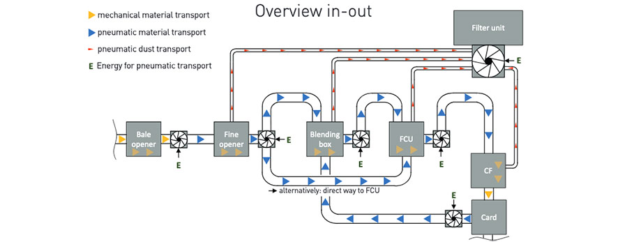
In the fiber preparation of nonwovens, in addition to the various mechanical processes, there’s also pneumatic fiber conveying. This takes place between a wide variety of units via pipelines, which are shown in Fig. 1 with blue arrows.When transporting fibers in nonwoven lines, for plant operators the focus is not only on blend quality and performance but also operational safety. The fans used for pneumatic fiber-transport are mostly oversized in their power to avoid pipe blockages and thus to prevent system downtimes. Furthermore, most of the fans cannot be regulated in speed and are constantly running at high speed and with high energy consumption.
The aim of the study was to build on this initial situation, an approach to increase energy efficiency within maintaining the floor quality of the card. An increase in energy efficiency must not be at the expense of the process safety, i.e. an increase in the probability of clogging.

Conveyance conditions as indicators for transport quality and efficiency
The efficiency of the fiber transport is the relationship of the product of volume flow and pressure loss. The fiber tufts constantly change their shape and their structural density during transport. The main influencing on the conveying condition are the consistency of the fiber-air mixture and the degree of opening of the fiber tufts.
- The consistency is influenced by the pipe cross-sectional area, the volume flow and the fiber mass flow.
- The degree of opening can be determined from the bulk density.
These factors have an effect on the pressure loss, which is mainly caused by the sliding friction of the fiber tufts in the horizontal pipe sections - because around 90% of the pipes run horizontally. In addition, there is sliding friction in the pipe elbows - the centrifugal force that acts here must be taken in account. Finally, the area of the fiber material in the air flow also influences flow resistance. To differenciate between the various conveying conditions, one can orientate oneself on knowledge from the bulk goods industry. With increasing conveying speed, a distinction is made between four basic conveying states. One speaks of plug to flight conveyance via the intermediate states of dune and strand conveyance (Fig.2). You have to note - fibers are compressible - which differenciates them from the vast majority of bulk materials - i.e., plug conveying is out of the question because the pipe would immediately clog. The challenge in handling fibers compared to bulk goods is that fibers have almost no momentum transmission. In addition, the entropy, based on the arrangement of the individual fibers within fiber tufts, is very large. The sliding friction decreases from the dune in the direction of flight conveyance in the horizontal pipe and increases in pipe bends. The most efficient conveying condition is considered to be strand conveyance (Fig.2).

An online measuring system as an "eye" for the detection of the conveying state
In order to differenciate the conveying states from one another, an online mesasuring system in connection with a sensor was developed as part of my master´s thesis. With the help of this measuring system, a closed control loop between the sensor and the fan is to be established in the future. The measuring system makes it possible to set the appropriate conveying state for every fiber type, mixture, length or every fiber titer. The measuring system is an infrared light grid with 119 individual beams (Fig.3). These are evenly distributed over the vertical pipe cross-section.

Depending on the activated detection zone - this can also be several zones at the same - the conveying states can be derived (Fig.4). in this way, the conveying state can be recognized in real time. This relatively simple model is not sufficient to reliably identify the delivery conditions. Here you have to use the individual beam evaluation and develop an algorithm in terms of software which can recognize the present conveying conditiony via distribution functions. To illustrate this, Fig.5. Here, 480 individual images are superimposed in each of the four images - similar to the principle of a long exposure. If you experiment with different degrees of opening, such as large and small tuffs, and additionally with two fan speeds (100% and 60%), the following can be seen in relation to the delivery head or the vacancy area in the pipe.
- At 100% fan power, the delivery head is the same for small and large tufts.
- 60% fan power, the pipe is filled to a third with large tufts, but half filled with small tufts.
Current status and outlook
The excerpts from the examinations shown illustrate the very strong influence of tuft size on the conveying condition. It is important to consider the variety of parameters this system has: from the fiber and pipe properties, pipe routing variants and the resulting flow resistances upstream and downstream of the pipes, to the types of fans and condensers used, etc. For the first time, an approach was chosen for the investigations which describes the influence of as many parameters as possible and thus enables a detailed detection of the conveying status. In the next step, in cooperation with the IT specialists of the AUTEFA Solutions Group, a software for a closed loop control is worked out so that a finished product is available promptly.